Warn A2500 Upgrade Install
Step by Step
This install assumes you know a little about taking your quad apart however there's nothing to getting the parts off for this install.
Tools Needed
10mm Socket
2 inch extension (3/8" recommended)
Ratchet Drive
7/16" wrench
7/16" socket
Flat (regular) Head Screwdriver
Philips (4 way) Head Screw Driver
Regular Pliers
Diagonal Cutters
Items for Install
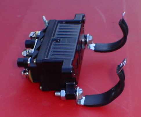
A2500 Upgrade Kit
(Should include #8 wiring (4 pieces), Contactor, Handheld Remote, Remote Socket
with wiring, and Remote Bracket)
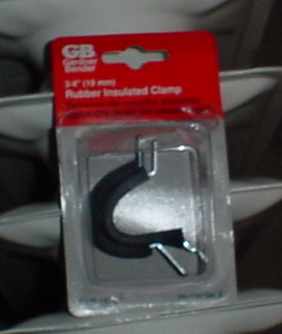
2 Gardner Bender 3/4" Rubber Insulated Clamp ($1.06 at Lowes) P/N:PPR-1575
#8 Wiring lugs (when you trim the wiring to the custom length)
Getting at the install:
I never installed my A2000 kit completely so I did not have to remove the solenoid
or the old wiring, however if you did not, UNHOOK the Battery before cutting
loose any wiring, that belonged to the old kit)
Step One
Unhook the battery and remove. (three 10 mm bolts is all that holds in the
battery)
Step Two
Remove the Plastic from around the Air Box
(Two Philips head screw on both sides at the front
fenders, remove the shifter knob and pull back and up on the cover) you may want
to remove the access panel before attempting this so you can see inside the
cover during removal.
Step Three
On the left side under the black rubber splash shield cut the wire tie free so you can
flap this up to run your wiring
Step Four
If you're doing an install and did not have to remove the old wiring you now
have to remove both splash shields from the left and right front wheel wells. Not hard all
that is required is a Philips screw driver and a pair of pliers.
Now to install
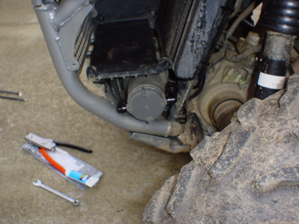
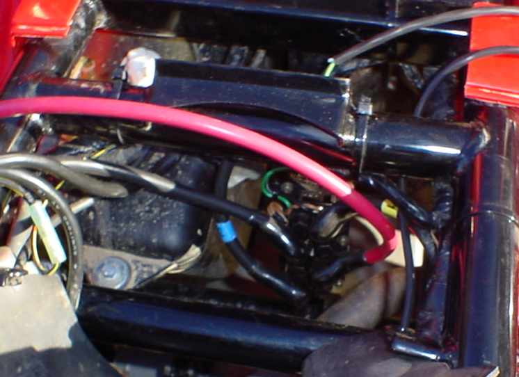
If you are going to go custom you have a couple of options for routing your wiring. WARN recommends you place your contactor near the rear of the quad. Guess what is here on the 650? The Vehicle Down Sensor is located here on the right hand side and on the left there is little room because of the exhaust. However there is a vertical frame member here that is made to order here. I used the 2 Gardner Bender 3/4" Rubber Insulated Clamps to hold mine here. Mounting here does not limit your ability to adjust the exhaust valves on the rear cylinder or does it make the it hard to get at the exhaust for that ever popular later exhaust swap.
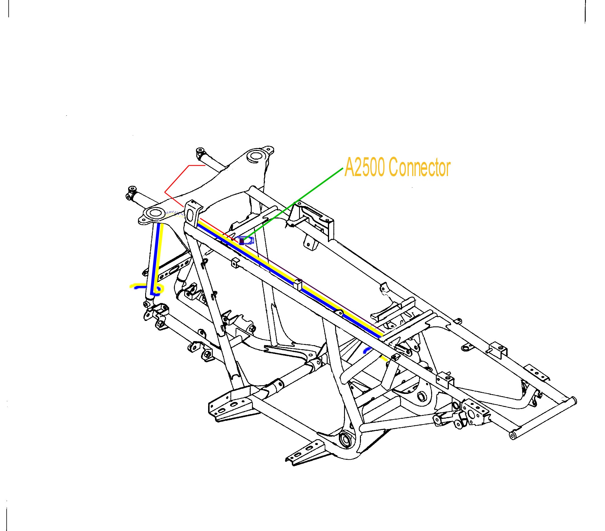
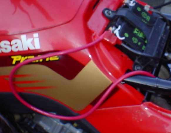
The next area is the mounting of the connector for the remote. I chose to mount mine in the air box and then add a toggle switch to the handle bars. Like I see it if you need the remote you need not be on the quad.
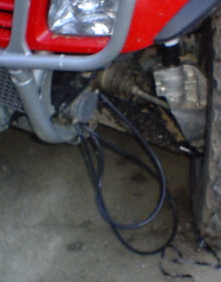
Next is wire routing I routed my wires down the left side of the frame down the radiator support and to the winch. This made for a nice unobstructed wiring job with nothing to rub the wiring. Next run the remote wiring and the toggle switch's wiring. (Note the excess from the remote if you mount in the air box is exactly enough to make it up the handle bars and to the toggle switch no added cost. Then finally route the power to the contactor. Trim all wiring so it does not rub or snag. Trim from winch and battery side preferably.